From Flat Stock to Fully Assembled: The Step-by-Step Fabrication Flow of a Self-Supporting Lattice Tower
The journey from raw steel coils to a fully assembled self-supporting lattice tower is a symphony of heavy fabrication, precision engineering, and meticulous quality control. A self-supporting tower is a spatial lattice structure assembled from hundreds or even thousands of angles and connection plates using bolts. Any deviation in a single connection hole may render on-site erection impossible. This is why the manufacturing process is governed by rigorous standards—typically GB/T 2694 for transmission towers or ANSI/TIA-222-H for telecommunications structures—and why every step, from flat stock to final packaging, is subject to systematic quality verification.

This guide walks through the complete fabrication flow, highlighting the critical quality control checkpoints that ensure every tower arrives on-site ready for smooth, efficient erection.
Step 1: Material Preparation and Cutting
The Process
The fabrication cycle begins with raw material receiving and inspection. High-quality low-carbon steel coils or angle steel sections are delivered to the factory. Upon arrival, materials undergo visual inspection for surface defects, by sampling for physical and chemical testing to verify mechanical properties and chemical composition against national standards. For power and telecom towers, materials such as Q235B, Q345B, or Q355B (high-strength low-alloy steel) are common, selected for their strength, toughness, and weldability.
For angle steel profiles produced from coils, the steel is uncoiled, leveled, and slit into narrow strips, then fed through a series of rolls in a cold-forming process to shape them into standard L-shaped angle profiles. This cold-working increases strength through strain hardening.
Cutting follows. The long angles are cut to specific lengths per tower design drawings using high-precision saw cutting or shearing. For steel plates used in gusset plates and connection nodes, cutting is performed using plasma, flame, or laser cutting machines, depending on thickness.
Quality Control Checkpoints
· Material certification: Mill test reports must confirm chemical composition and mechanical properties
· Dimensional accuracy: Cut lengths must match design specifications; errors here compound through subsequent steps
· Edge quality: Burr-free, square ends ensure proper fit-up during assembly
· Material traceability: Each batch is tagged and tracked through the entire production flow
Step 2: Punching and Drilling — The Critical Hole-Making Step
The Process
Hole-making is arguably the most critical step in tower fabrication. The entire bolted connection philosophy of a lattice tower depends on hole positions being accurate to within tight tolerances. There are two primary methods:
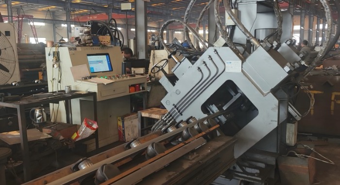
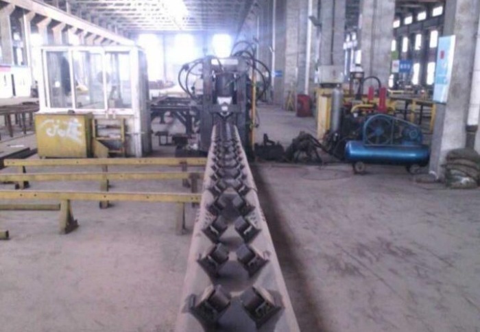
CNC Punching: For most standard-size angle steel, manufacturers use CNC angle production lines for punching. This automated equipment integrates feeding, conveying, punching, and shearing, driven directly by data generated from lofting software—eliminating manual measurement and marking entirely. CNC technology ensures every component is identical, eliminating assembly errors and ensuring structural integrity.
CNC Drilling: For thicker sections (typically angle steel with leg thickness exceeding 14mm) or where higher hole wall quality is required, drilling is preferred. Drilling produces no impact tearing effect on the base metal, resulting in higher surface smoothness on hole walls.
For connection plates (gusset plates), holes are produced using hydraulic presses with multiple die stations, capable of punching, drilling, and even marking in a single setup.
Quality Control Checkpoints
· Hole position accuracy: CNC systems maintain hole placement accuracy that manual operations can never match
· Hole diameter and roundness: Monitored during production by quality inspection personnel
· Deburring: Hole edges are deburred to prevent stress concentrations and ensure smooth bolt insertion
· 100% first-article inspection: The first piece from each production run is fully measured before mass production proceeds
Step 3: Cold Bending and Forming
The Process
Certain components—such as bracing members, curved connections, and cross-arm profiles—require bending beyond the standard angle profile. Cold bending is predominantly used, where steel is formed at room temperature using hydraulic presses or rotary draw benders. This method is efficient and preserves the material's properties.
For very thick sections or tight radii, hot bending (heating the steel to a specific temperature to make it pliable) may be employed, though it is less common for standard angles.
Additional forming operations include:
· Cutting angles: Removing material to create clearance for connections
· Opening/closing angles: Adjusting the angle between legs
· Flattening: Compressing the end of a member for connection fit-up
· Root cleaning: Removing weld root material for proper joint preparation
· Back shaving: Machining the back side of angle legs for flush connections
Quality Control Checkpoints
· Bend radius and angle: Verified against design specifications
· Surface integrity: No cracking or excessive thinning at bend locations
· Dimensional stability: Formed components must maintain shape through subsequent handling
Step 4: Assembly and Welding (Sub-Assembly)
The Process
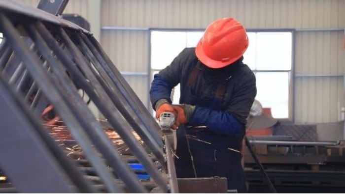
While the primary tower structure uses bolted connections for field assembly, smaller sub-assemblies—such as connection plates, stub ends, ladder supports, and equipment platforms—are welded in the factory.
Skilled welders use processes including SMAW (Shielded Metal Arc Welding) or the more efficient FCAW (Flux-Cored Arc Welding). All welding is performed to qualified Welding Procedure Specifications (WPS) , with welders certified to the specific procedures they execute.
For critical load-bearing welds, 100% non-destructive testing (NDT) is implemented. For towers that will be hot-dip galvanized, weld quality is particularly important because galvanizing will not hide defects—it can actually reveal porosity or slag inclusions through zinc leakage.
Quality Control Checkpoints
· Visual inspection: Weld appearance, profile, and undercut are checked by authorized personnel
· NDT methods:
Ultrasonic Testing (UT) : Inspects internal defects such as lack of fusion, cracks, and slag inclusions
Magnetic Particle Testing (MT) : Detects surface and near-surface cracks
Penetrant Testing (PT) : For non-ferromagnetic materials or as an alternative for surface defects
· Hold point requirement: All weld inspection and testing must be undertaken a minimum of 48 hours after weld completion
· Quality traceability: All inspection records are archived in the quality traceability system
Step 5: Hot-Dip Galvanizing — The Corrosion Protection Crown Jewel
The Process
After fabrication, every component undergoes hot-dip galvanizing (HDG) . This process provides a metallurgical bond between zinc and steel, offering superior, long-lasting protection against corrosion. The galvanizing sequence follows a strictly controlled process:
Degreasing/Caustic Cleaning: Removes organic contaminants like oil, grease, and dirt
Pickling (Acid Bath): Immersion in diluted hydrochloric or sulphuric acid to remove mill scale and rust, exposing perfectly clean steel
Fluxing: Components are dipped in a zinc ammonium chloride solution to prevent oxidation before galvanizing
Galvanizing: Immersion in a bath of molten zinc at approximately 450°C (840°F)
Cooling/Quenching: Controlled cooling to stop the reaction and solidify the coating
Quality Control Checkpoints
· Pre-galvanizing inspection: Surface preparation must be complete and uniform before dipping
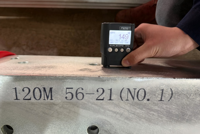
· Coating thickness: Measured using magnetic or electromagnetic gauges; minimum thickness per ASTM A123 or GB/T 13912 (typically 85 μm for structural steel, with enhanced thickness for severe environments)
· Coating appearance: Must be continuous, relatively smooth, and free from flux staining, uncoated areas, blisters, and gross dross inclusions
· Adhesion testing: Hammer tests or cross-cut tests verify coating bond strength
· Uniformity testing: Copper sulphate dip tests (Preece test) check for uncoated spots
· Rejection and rework: Any components failing inspection are marked, isolated, and returned for re-galvanizing
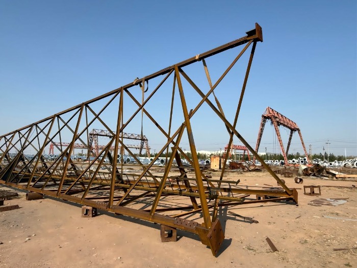
Step 6: Trial Assembly — The Final Technical Checkpoint
The Process
Trial assembly is an irreplaceable quality verification step in tower manufacturing and the final technical checkpoint before delivery. It is typically conducted on a dedicated assembly platform, precisely leveled to simulate the actual installation reference plane.
Workers follow erection drawings and bolt lists strictly, using bolts and washers identical to those used on site, to assemble main members, diagonals, horizontals, and secondary members piece by piece. For each production batch, representative tower sections or complete tower heads and body nodes are selected for factory pre-assembly.
Quality Control Checkpoints
During trial assembly, quality engineers focus on:
· Overall geometric deviations: Tower body width, diagonal differences, cross-arm level differences
· Connection joint fit-up: Verification that root cleaning, back shaving, and hot bending results meet standards
· 100% bolt pass-through rate: Reaming or forced driving is strictly prohibited; every bolt hole must accept its bolt without force
· Accessory compatibility: Ladders, platforms, cable supports, and antenna brackets are verified for connection compatibility
After assembly, laser rangefinders, theodolites, and specialized measuring tools are used for comprehensive measurements. Every data point is recorded, and photographic records are taken. If any deviation is found, the team immediately traces back to the responsible process and implements corrective actions until all design tolerance requirements are fully met.
Once trial assembly is passed, components are numbered according to erection sequence, disassembled, and prepared for delivery. This step fundamentally eliminates on-site erection uncertainties. Especially for export projects, identifying and solving problems domestically ensures towers arrive on site ready for smooth and efficient erection.
Step 7: Packaging and Shipment
The Process
After successful trial assembly and disassembly, components are packed for shipment. The packaging strategy must protect the hot-dip galvanized coating from damage during transport while maximizing container utilization.
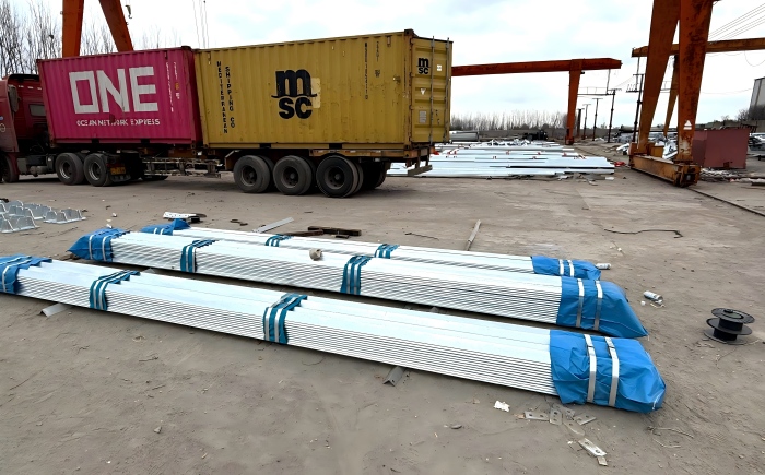
For angle steel towers, the modular nature of the design enables exceptionally efficient packaging. Unlike welded monopole sections that occupy fixed, bulky shapes, angle steel members nest together with high density. Typical packaging methods include:
Plastic wrapping: For corrosion protection during sea freight
Steel frames or crates: For structural protection of heavy components
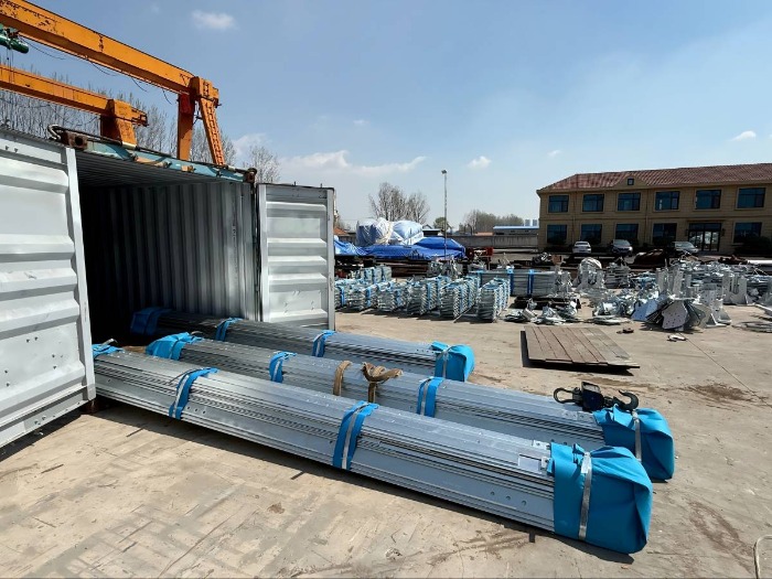
Custom container frames: Precisely dimensioned to 20-foot or 40-foot containers, with load-bearing beams and hanging points matched to container interior dimensions
Components are packed with assembly instructions and all necessary hardware—anchor bolts, nuts, washers—included. For international shipments, detailed packing lists and customs documentation are prepared.
Quality Control Checkpoints
Component count and identification: All parts verified against packing lists
Coating protection: Galvanized surfaces protected from abrasion during transport
Labeling: Clear identification of each component, correlating to erection drawings
Container loading optimization: Maximizing weight and volume utilization while ensuring stability during transit
Conclusion
The fabrication of a self-supporting lattice tower is a systematic process where quality is not inspected in at the end—it is built in at every step. From the initial material certification to the final trial assembly, each operation is governed by qualified procedures, executed by skilled personnel, and verified through rigorous inspection. The trial assembly, in particular, serves as the ultimate proof of manufacturing precision: if the tower fits together on the factory floor, it will fit together in the field.
For project owners and network operators, understanding this fabrication flow provides confidence that the tower arriving on site is not just a collection of steel pieces, but a precisely engineered structure that has been proven—bolt by bolt—to assemble correctly, stand reliably, and serve its mission for decades.
Ready to discuss your next tower project? Contact our engineering team today for custom design, fabrication, and quality assurance planning.


评论
发表评论