Electromagnetic Shielding Between Co-Located Operators on a Single Monopole
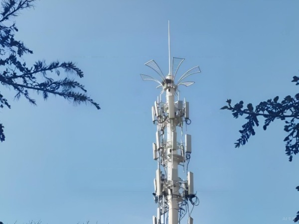
As mobile network operators race to deploy 5G and expand coverage, the pressure to share infrastructure has never been greater. Tower sharing—placing multiple operators' antennas on a single monopole tower—dramatically reduces capital expenditure, accelerates rollout timelines, and minimizes the proliferation of unsightly towers. However, co-location introduces a critical technical challenge: electromagnetic interference (EMI) between closely positioned antennas. Unlike structural conflicts resolved with steel reinforcement, interference is invisible, frequency-dependent, and can cripple network performance if not properly managed.
This blog examines the physics of antenna-to-antenna coupling on a shared monopole, explores the engineering parameters that determine required isolation, and presents the three primary mitigation strategies—antenna spacing, physical barriers, and PIM-optimized hardware—that enable multiple operators to coexist on a single structure without degrading each other's networks.
The Interference Problem: When Operators Share a Tower
When antennas from different operators are mounted on the same monopole, each transmitting antenna radiates energy that can couple into neighboring receiving antennas. This unwanted coupling, quantified by isolation, manifests as interference that reduces cell receive sensitivity, degrades signal-to-noise ratio, and—in severe cases—blocks calls entirely.
The challenge is compounded by three factors unique to co-location:
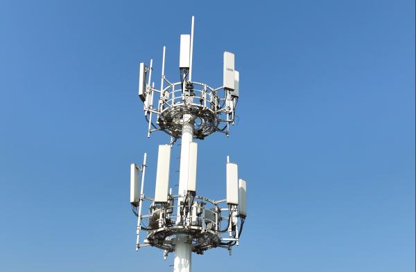
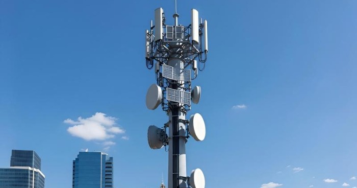
· Proximity: Unlike operator-owned towers where antennas can be widely separated, shared monopoles force antennas into close quarters. Multiple platforms are typically spaced only 5 meters apart in standard tower designs, which may be insufficient for certain system combinations.
· Frequency Diversity: Different operators deploy different technologies (GSM, CDMA, LTE, 5G NR) across multiple frequency bands. Coupling can occur even when systems operate on different frequencies, through mechanisms like passive intermodulation (PIM) where multiple signals mix to create spurious harmonics that fall into another operator's receive band.
· Dynamic Loading: As operators add capacity—more sectors, more antennas, more carriers—the interference environment evolves, requiring isolation designs with built-in margin for future expansion.
The industry standard for co-location antenna isolation is 30 dB minimum, measured as the power ratio between the signal fed into one antenna and the signal picked up by the other. Achieving this target across the diverse frequency combinations present on a shared monopole requires deliberate engineering across three interacting dimensions: vertical separation, horizontal separation, and physical barrier implementation.
The Physics of Isolation: How Antennas Couple
Before exploring mitigation techniques, understanding how antennas interact is essential. In co-location, coupling occurs through two primary mechanisms:
Near-field coupling: In close proximity (within a few wavelengths), antennas directly exchange electromagnetic energy through mutual impedance. The coupling strength decreases with distance but can remain significant even at separations of several meters.
Far-field coupling: As distance increases, antennas interact through radiated fields. Energy from a transmitting antenna's sidelobes—unintended radiation outside its main beam—can be captured by a neighboring antenna's main lobe or sidelobes.
The key insight for engineers is that vertical separation is dramatically more effective than horizontal separation at achieving the same isolation. With antenna spacing held constant, vertical mounting delivers substantially greater isolation than horizontal mounting. For vertical separation, the required distance between antenna centers is inversely proportional to the frequency: lower frequencies require significantly greater spacing. For example, a Chinese study showed that the required vertical isolation distance between CDMA 1X and GSM900 systems reaches 9.7 meters—and when antenna dimensions are considered, the total platform separation must exceed 11.7 meters. This far exceeds the typical 5-meter platform spacing in standard tower designs, revealing why many existing towers are structurally insufficient for multi-operator hosting.
The implication is that isolation cannot be achieved through horizontal separation alone. Optimizing multi-operator layouts requires leveraging the superior efficiency of vertical separation while minimizing platform count, tower height, and structural cost.
Strategy One: Antenna Spacing — Vertical and Horizontal Separation
The most fundamental method for achieving isolation is simply increasing distance between antennas. Placing antennas farther apart reduces coupling in inverse proportion to distance, and for most bands, a half-wavelength separation (approximately 0.4-0.5λ) is sufficient to prevent significant coupling between closely spaced elements.
Within this strategy, engineers must choose between two placement approaches:
| Separation Type | Typical Requirement | Efficiency | Advantages | Challenges |
|---|---|---|---|---|
| Vertical | 1–10+ meters depending on frequency bands | Superior | No additional platform structure; leverages existing tower height | Requires multiple platform levels; limited by tower height |
| Horizontal | 0.5–4.5 meters on same platform | Inferior | Uses single platform; no extra tower elevation required | Platform must be wide enough; limited by physical real estate |
For horizontal separation, practical guidance from industry antenna installation standards provides clear benchmarks:
Dual-polarized antennas (±45°): 20–30 cm spacing (polarization orthogonality provides inherent isolation)
Directional antennas (single platform): ≥2.5 meters
Omnidirectional antennas (single platform): ≥4 meters
Same-cell diversity receiving antennas: ≥3 meters
Transmitting and receiving antennas across platforms: ≥1 meter vertical spacing
For vertical separation, no fixed rule applies—the required distance must be calculated based on the specific frequency bands, transmit powers, and receiver sensitivities of the operators sharing the tower. Vertical separation is preferred whenever site conditions permit, as it delivers greater isolation per meter of separation distance.
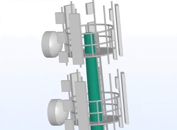
The most effective architecture for shared monopoles is a tiered platform system, where each operator's antennas are assigned to a dedicated platform level. This provides clean vertical separation between operators while allowing each to optimize their antenna orientations within their allocated tier.
Strategy Two: PIM Mitigation — Guarding Against Passive Intermodulation
PIM is a major issue in cellular networks. As multiple operators add equipment to a shared tower, they inevitably introduce new passive components—connectors, cables, mounts, jumpers—into the RF chain. Each of these components, if improperly installed, made from ferromagnetic materials, or subject to corrosion, can become a source of nonlinearity.
When two or more high-power downlink signals pass through a nonlinear passive junction, they mix to produce new frequencies. If any of these spurious products fall into an operator's receive band, they appear as interference that can block calls or severely reduce receive sensitivity.
PIM is particularly insidious in co-location scenarios because its effects appear unpredictably. A site may test clean at commissioning, only to develop PIM months later as connectors oxidize, mounts loosen, or torque is lost. Because PIM is generated at the tower top, diagnosing it requires specialized PIM test equipment and often involves climbing to each connection point.
Standards bodies such as the GTI (Global TD-LTE Initiative) have published extensive coexistence studies addressing PIM and other interference mechanisms between multiple operators sharing spectrum and infrastructure, including guard band requirements and synchronization frameworks for TDD networks.
Commercially, the industry has responded with PIM-optimized hardware. Companies like ANDREW (an Amphenol company) offer specialized monopole platforms engineered specifically to mitigate PIM in multi-operator environments. These platforms feature:
Optimized sector-to-sector spacing: Extended frames increase antenna-to-antenna separation without requiring additional tower height.
Extended mounting spines: 10-foot spines provide dedicated mounting zones for RRUs (Remote Radio Units), physically separating active radios from antenna connection points to reduce PIM coupling pathways.
Specified hardware materials: All brackets, pipes, and hardware are manufactured from non-ferromagnetic materials and undergo PIM qualification testing to ensure they do not introduce additional intermodulation sources.
These PIM-optimized platforms are typically rated for high capacity—capable of hosting up to three sectors with multiple antenna pipes per sector—and are designed to be compatible with PIM-Guard mounts that further reduce interference potential at RF connection points.
Strategy Three: Physical Barriers — Baffles, Shields, and Absorbers
When spacing is limited or PIM controls are insufficient, physical barriers provide an additional layer of isolation. These take three primary forms:
Metal Baffles and Shield Walls
Patented antenna shielding methods specifically address interference between co-located antennas on towers. These devices use strategically positioned conductive surfaces to create localized isolation zones, allowing antennas to be placed closer together than would otherwise be possible without coupling. For Massive MIMO arrays, shield walls between individual antenna modules must provide at least 20 dB of X-POL and CO-POL isolation to meet minimum performance requirements.
Mantle Cloaking (Emerging Technology)
Advanced research has demonstrated that properly designed mantle cloaks—patterned metallic sheets placed around cylindrical monopoles—allow tightly packed antennas to operate as if isolated in free space. This approach enables antennas placed as close as 1/10 of the shorter operational wavelength, offering a potential path toward dramatically higher packing densities on existing monopole structures.
Radar Absorbing Material (RAM)
RAM can be deployed as isolation barriers between antennas on the same platform. These materials convert incident electromagnetic energy into heat, reducing the energy available for coupling into neighboring antennas. RAM barriers can be combined with dielectric-loaded corrugations to extend isolation capabilities into lower frequency bands where conventional RAM has limited effectiveness.
Integrating dielectric-loaded corrugations with RAM extends the barrier's effectiveness into the lower frequency range, creating a hybrid structure that combines broad-spectrum absorption with frequency-selective reflection.
However, no single solution works universally. The selection of physical barrier technology depends heavily on the specific frequency bands involved, the achievable separation distance, and the available mounting real estate on the platform.
Comparative Overview: Antenna Separation vs. Physical Barriers
A comparison of the primary isolation approaches helps clarify the design trade-offs:
| Isolation Parameter | Vertical Separation | Horizontal Separation | PIM-Optimized Platforms | Metal Baffles / Shield Walls |
|---|---|---|---|---|
| Primary Mechanism | Increased 3D distance | Increased horizontal gap | Minimized PIM sources | Directed reflection / absorption |
| Effectiveness per Unit Distance | High | Low | N/A (PIM-specific) | Moderate |
| Adds Tower Height? | Yes | No | No | No |
| Consumes Platform Real Estate? | No | Yes | Yes | Yes |
| PIM Reduction? | No | No | Yes | No |
| Typical Cost Impact | High (tower extension) | Moderate (wider platform) | Moderate | Low to moderate |
| Best For | Different frequency bands | Same-band co-location | High-power sites | Band-limited isolation needs |
Structured site surveys integrating these approaches are essential. Each operator must provide detailed specifications: transmit power per carrier, receive sensitivity, operating frequency bands, and antenna radiation patterns. These inputs are then used to compute:
Required vertical isolation distance (via propagation models for each operator-operator pair)
Required horizontal isolation distance (if vertical spacing is constrained)
Residual interference after spacing—determines whether baffles or RAM are needed
PIM analysis (based on transmit power levels and connector types)
This analytical process is non-negotiable. Installing baffles or increasing spacing without a clear model of coupling mechanisms can lead to over-engineering (wasted cost) or under-engineering (interference that appears after commissioning).
Site Survey Integration: An Engineering Checklist
For network planners and tower owners, achieving reliable multi-operator isolation requires a disciplined process:
Gather operator specifications: Transmit power per carrier, receive sensitivity, operating bands, antenna radiation patterns.
Calculate required isolation using standardized models (e.g., TIA procedures for isolation measurement between collocated antennas).
Determine spacing requirements: Vertical vs. horizontal—prioritize vertical where possible.
Check residual interference: If spacing alone cannot meet 30 dB isolation, specify baffles or RAM.
Verify PIM controls: Ensure all mounts and connectors are low-PIM certified and that installation crews are trained in PIM-safe practices.
Test after commissioning: Perform PIM testing and isolation verification before declaring the site operational.
The importance of verification cannot be overstated. PIM is a major issue in cellular networks, caused by equipment aging, adding new equipment, and poor installation practices. A site that passes isolation requirements at day one may fail months later due to connector corrosion or mount loosening.
Conclusion
Multi-operator co-location on a single monopole is an economic and environmental necessity in modern network deployment. However, the invisible challenge of electromagnetic interference—antenna coupling and PIM—demands the same engineering rigor applied to structural load calculations.
Achieving reliable isolation requires a balanced approach combining three core strategies: maximizing vertical separation, deploying PIM-optimized mounting hardware, and using physical barriers where spacing is limited. Each strategy has its domain of optimal application, and the correct balance depends on the specific frequency bands, power levels, and physical constraints of the site.
The industry standard of 30 dB isolation is achievable on shared monopoles—but only through deliberate, data-driven engineering. Operators who invest in proper isolation design at the planning stage avoid the costly rework of retrofitting shielding after interference has already disrupted service. In the shared infrastructure era, good neighbors don't just share steel—they share the electromagnetic spectrum without stepping on each other's signals.
Learn more at www.alttower.com


评论
发表评论